Lorenzo wrote up this wonderful Instructable / DIY HowTo on Making a Voltage Divider for Monitoring Solar Panels and Batteries.
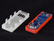
 You’ll find this helpful to understand more of what goes into your Valarm remote monitoring boxes. Like those that use the Internets of Things devices and sensors to monitor air quality, water, and vehicles.
You can use the Step-by-step tutorial to make your own Industrial Internet of Things / IoT Applications with sensor devices from Shop.Valarm.net, connected to the Internet of Things cloud gateway Tools.Valarm.net.
There are already plenty of guides and Instructables outlining the concepts and circuit diagrams for voltage division using simple resistors. And there are certainly a few showing very simple physical circuits using alligator clips and/or breadboards. I thought it might be nice to show a simple, physical build of a real-world, useful voltage divider. As such, we won’t really be covering the theory, or the math. For that I recommend any of the other fine Instructables on the subject, or my favorite interactive calculator for deciding which resistors to use, is Sparkfun’s excellent tutorial on voltage dividers.
Remember, this is a divider, not a regulator. It divides an input voltage by a fixed factor, it doesn’t force a varying input voltage to a fixed output voltage. It cannot and should not be used to power any device that requires more power than a small LED – it’s designed really for a high-impedance input, like a voltmeter (or multimeter) or a voltage sensor that’s part of a larger system.
At Valarm, where we supposedly “Monitor Anything, Anywhere”, we use this particular design (and input/output values) to measure solar charging systems. The output of a solar panel intended to charge a 12V battery can be as high as 22V! And the output of the charge controller to the 12V battery can be as high as 16V (though ~14V is more typical).
In order to read high voltages into A-D inputs that can only tolerate lower voltages (in our case a Yoctopuce 0-10V USB sensor), we need to divide those voltages down to something less (10V in our case). You might be reading these into a 5V or even 3.3V Arduino analog-in, for example. In that case you’ll need different resistor values from the ones we used.
 Step 1: Bill of Materials
We need two different input ranges for our unit, one for the solar panel and one for the battery. But we’ll just start with the higher input (22V) from the solar panel since the steps are the same.
1. 1x small proto-board, this Uxcell branded board worked nicely and has room for two of our dual-channel dividers.
2. 2x Screw terminals. These sure are convenient, sturdy, very useful for real-world installations.
3. Resistors. We keep a big box of many values around all the time. For our 22V Max circuit, we’re using a 10K on the 1st stage and 8.2K on the second stage.
4. Jumper wire. The coil of twisted-pair wire in the photo is clipped out of an ethernet cable – an excellent source of easy-to-use solid copper jumper wire!
 Step 2: Place your screw terminals
We like to leave some space above the screw terminals for a label, and on either side of the terminals for clips to anchor the finished board to the back-panel in a larger enclosure.
Finally, just be sure to leave enough space between for the resistors.
 Step 3: Solder the terminals down
Flip the protoboard over and lay it on your work surface so the screw terminals are pushed up through the protoboard and conveniently held in place for you to solder.
We’re just tacking them down here, so they don’t fly all over while we’re mounting the rest of the pieces.
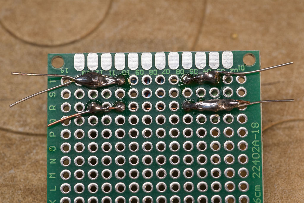
 Step 4: Add the resistors and jumper
Gently pre-bend your resistors into a U-shape and push them through the holes in the proto-board closest to the terminals.
 In these photos, the 10K resistor is on top, and the + input (positive high) is at the top-left screw. The + output (positive low) is on the top-right.
The negative/ground input is at the bottom-left. The 8.2K resistor is connecting the positive output to the ground.
 Finally the negative/ground output needs to be connected across the two screw terminals. We use our copper jumper wire for this.
In the pics I’m stripping the tiny “borrowed” ethernet wire with a pair of automatic wire strippers that are the greatest thing since sliced bread.
 Simply push the resistor leads and the wire through the proto-board and bend them across the back to hold them in place (photos in next step).
Make sure they lay nice and flat on the front side of the board.
 Step 5: Solder everything down
In the first photo you can see the unsoldered resistor leads and ends of the jumper wire coming through the proto-board.
 The unsoldered resistor leads are touching the appropriate studs beneath the screw terminals.
Second photo, they’re all soldered to each other.
Then there’s the 3rd photo.
 In the third photo hey’re trimmed with the cutters absolutely everyone should own.
You’re almost finished. Ready for the last step?
Step 6: Finished! Test it!
 Here’s the finished product.
A second channel has been added with different resistors to get a different divider (this one for the battery input mentioned during the intro).
We’ve also added labels for easy reference.
We love using our fav little label maker, the Epson LW-400.
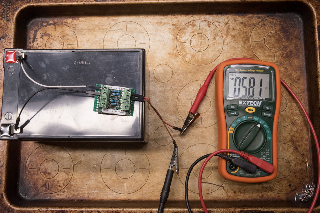
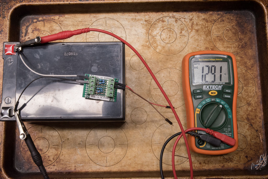 In the pics you can see our battery is reading a reasonably healthy 12.91V all by itself.
And when passed through the voltage divider it’s 5.81V, exactly the ratio we’re expecting!
Once this voltage is being read into your hardware (again, in our case it’s a Yoctopuce 0-10V USB module), you can scale it back up to the “real” voltage in software. Maybe that’s in your Arduino sketch. Or if you’re using Valarm Tools with a Yoctopuce Sensor Hub, the transformation is easily configured in the Device Manager under the Data Path -> Linear Scalers configuration.
 I hope that’s helpful. Whether you’re using the voltage divider circuit in:
- A full-blown Valarm Remote Monitoring system
- Arduino or C.H.I.P. system
- Or alongside an A-D shield over a Raspberry Pi
We think it’s a great idea to build it into a sturdy, reusable little package like this.
 You now know more about key components that go into Valarm remote monitoring boxes!
Watch our videos for more on Industrial Internet of Things devices for example applications.
Have a look at these Industrial Internet of Things Customer Stories. You’ll see how these components are critical in real world examples of sensor telemetry.
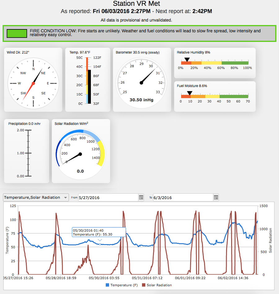
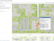
 Industrial IoT applications need knowledge of real-time voltages of solar panels and battery health.
Web dashboards monitor solar panel and battery voltages.
You can see your Industrial IoT Sensor dashboards on any of your mobile devices that have a web browser, like your phone or tablet.
Questions?
If you’ve got any questions about remote monitoring, the Internet of Things, sensors, telemetry, or anything else, please don’t hesitate to Contact Us and Info@Valarm.net
Happy Monitoring with Industrial Internet of Things / IoT Devices & Sensors!!