Water is a precious asset. It is critical for various industries and we humans need it every day. Effectively monitoring and managing water resources has grown in importance over time. We’re witnessing 1st hand just how much water monitoring needs are steadily increasing among our customers.
 From water wells, tanks, and levees, to rivers, coastal flooding, and any other industry dealing with water, we’re continuously integrating more Industrial IoT sensors for monitoring water. In this write-up, we’ll discuss additional flow meters you can cost-effectively monitor with Tools.Valarm.net. Whether you need to monitor water sensors made by Senix, Flowline, McCrometer, Geokon, Seametrics, EKM, or any other hardware manufacturer, our customers monitor them all. There are various types of flow meters, like magnetics made by Seametrics and McCrometer, mechanical impeller / propellers made by McCrometer, EKM, and other hardware manufacturers. Today we’ll talk more about ultrasonic flow meters.
In this article, you’ll learn the nitty gritty details of how to monitor TUF-2000 ultrasonic flow meters with sensor hubs connected to RS-485 Modbus sensor adapters. As with other monitoring deployments, you’ll need to figure out which internet connectivity, power source, enclosures, and so on will work best for your specific deployment scenarios. Have a look at our Customer Stories page and don’t hesitate to get in touch with us at Info@Valarm.net if you’ve got any questions or would like any advice.
To get started with monitoring these TUF-2000 series flow meters, you’ll need the following:
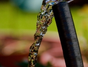
 TUF-2000 series flow meters like the TUF-2000S, or other fix mountable, explosion proof, or the wall mountable version you see in the the pictures in this story
- Flow transducers compatible with TUF-2000 flow meters to monitor flow and/or temperature, like the clamp on transducers you see in the photos
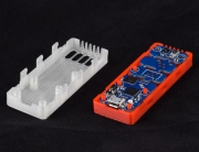
- Sensor Hubs to upload your sensor measurements to the clouds via GSM mobile cell network, ethernet, WiFi or other internet connectivity
- RS-485 sensor adapters to connect and communicate with your flow meters

After you’ve linked your sensor hubs to Tools.Valarm.net, you’ll connect your RS-485 sensor adapters to your TUF-2000 series flow meters.
You’ll do this by connecting a wire of your choice from the + (positive) 485 on your flow meters to the positive (+) on your RS-485 sensor adapters.
Similarly, use a wire to connect the negative (-) channels on your flow meters and your RS-485 sensor adapters. You’ll see in the photos that we found that using red and black cables for this makes it easy to remember and keep track of.
 Remember to configure and follow your flow meter instructions, following and configuring the required settings if you haven’t already, things like – transducer type, liquid type, mounting type, pipe outer diameter, pipe material, and pipe wall thickness. And also confirm that you have a strong signal strength and quality for your water transducer installation to make sure you have reliable measurements and readings.
Now after you’re wired up, plug your Yoctopuce RS-485 sensor adapter into your computer. Make sure your flow meter is also powered up and that your RS-485 is connected up with the positive and negative leads matching up to your flow meter.
Fire up your virtualhub software and point your browser to http://localhost:4444. Click the menu button ‘configure’ for your RS-485 sensor adapter.

 Make sure that your RS-485 sensor settings here match what you set on your TUF-2000 series flow meter. We recommend you use the following RS-485 Modbus settings:
- Modbus RTU
- 9600 Baud
- 8 data bits
- No parity
- 1 stop bit
In short hand that’s RS-485 Modbus RTU with 8N1 at 9600 baud.

 Next up we’ll create a job file that will program your RS-485 sensor adapters to automatically query your flow meters as often as you need. Then your flow meter measurements will be uploaded to Tools.Valarm.net.
Click the manage job files button in your RS-485 virtualhub settings window to make a new job file.
Click define a new job to make a new job file.
 Then click add step to add a new task to your newly created job file. You can see in the examples that we named ours flowtuf.job task1.
Next up you’ll edit your 1 and only task.
You’ll set the your task to periodic so that your flow meter sensors send data at pre-defined intervals.
Configure your task to use a custom protocol as you see in the screenshots.
You’ll add a step for each variable you want to query from your flow meter.
You’ll look at your TUF 2000 series flow meter documentation to find which Modbus register you need to query based on which measurement you want from your flow meters.

We’ve included screenshots from a manual we found while searching the web. In these examples we’ll query flow rate, velocity, and the positive accumulator / total flow usage. Now how do we use each MODBUS query for the specific flow meter Modbus registers?
For each variable you want to query you’ll find the register number in the flow meter manual, then subtract 1. Then convert that decimal number to hexadecimal using any converter like those you’ll find by searching the web. Let’s go through some examples.
In our example screenshots you’ll see that we are querying for the register variables:
 Flow rate (Register 0001) means we want to convert 1 – 1 to hex. So that’s 0 to hex, which our hex converter tells us is 0, so that’s an easy one to start with.
- Velocity (Register 0005) means we’ll convert 5-4 to hex. 4 in hexadecimal is simply 4.
- Total Flow Usage / Positive Accumulator (Register 0115) means we’ll convert 0114 from decimal to hexadecimal. 0114 in hex is 72.
 Now let’s set up the tasks to query for those registers.
Add a step for each variable you want to query. For example if we want to query the positive accumulator for total flow usage then you’ll use the writeMODBUS command with the argument:
010300720002
Note the 72 in the middle of the argument. That’s the key that you’ll need to change for any other variable you want to query. For example, you’ll see in the screenshots that the other two Modbus commands we’re sending have 04 and 00 in the command argument instead of 72. So replace those 2 digits with whichever register you need to query.
Now after you’ve queried for a register you’ll need a place to store and save the flow meter sensor’s response to your query. We’ll do this with an expect command.
 Add a step for an expect command with the argument:
:010304($1:FLOAT32X).*
Important: Note that the $1 is telling the sensor adapter to store this sensor query in generic sensor variable 1, which we’ll later map and associate with a column / field on Tools.Valarm.net.
As you see in the screenshots, if we want to query multiple registers and store them in different sensor fields then change the expect command to $2 for genericSensor2, $3 for genericSensor3, and so on. You’ll experiment and play with this until you get just what you, your teams, and your organization need from your industrial sensors.
Also note that in the flow meter documentation with the registers you see there is the register number and also a format. If the format is REAL4 in the docs, then you’ll use the FLOAT32X data type you see in the screenshots. However, if you need to query a different type format, then get in touch with us, since you’ll need the latest RS-485 firmware and will use other data types like DWORDX for Modbus registers that are type LONG.

Once you’ve added all of the steps you want to query for the flow meter variables you need, then set a repeat interval in your job file. You’ll see in the screenshots that we set ours to query every 5 seconds. Based on how overwhelmed and inundated with information you want to be, you might query your sensor every 60 seconds, 300 seconds / 5 minutes, or whichever time interval works best for you and your monitoring deployments in the field.
Save your job and click run to start in running. You’ll probably want to set your job file as your startup job using the dropdown in the main RS-485 menu. You can see that we’ve done this in the screenshots here.
After you’ve saved all of your settings, you can power cycle your RS-485 sensor adapter, or unplug it and plug it back in to make sure it’s running how you want whenever it gets booted up. By clicking a sensor’s serial number in the virtualhub main window you can see the conversation that a serial interface is having with a device. You’ll see the commands and responses live and first hand. This is a nice way to confirm that everyone’s shaking hands, talking, and behaving how you’d like.

You can also click show device functions in the main virtualhub window to see live results of the latest flow meter sensor measurements that are being stored into your generic sensor X columns that are being uploaded to Tools.Valarm.net.
Now your RS-485 Modbus sensor adapters are configured to talk nicely with your flow meters. Let’s go over how to manage, map, analyze, and view your real-time water monitoring information from any device with a web browser pointed at Tools.Valarm.net.
After you’ve followed this video and configured and linked your sensor hub to Tools.Valarm.net, you’ll remember the sensor map tab under hub configuration.
 Now under that sensor mapping tab you’ll see your RS-485 sensor adapter under the last reported sensors. You can click add to add each of the generic sensors that you stored a flow meter register value in. In our case with the examples you’ve seen in this blog story, we saved flow rate, velocity, and total flow usage / positive accumulator in the genericSensor 1, 2, and 3 variables, respectively.

You’ll map your sensor variables to the columns that work best for you, for example the calc columns or the user columns that we used in the examples for the screenshots you’re looking at.
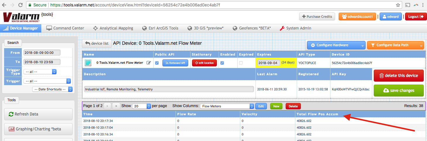
That’s it. Now you’ll see your flow meter sensor values are being uploaded to Tools.Valarm.net. However often you’ve set your sensor hub to upload is how often you’ll see new data uploaded. You can tie this in with how often your job file queries your flow meter.

For example, if you’re uploaded every 15 minutes to Tools.Valarm.net, then you’ll only need to query your flow meter with your job file every 900 seconds.
One more convenience we can configure is to use the custom column re-naming / aliasing features of Tools.Valarm.net. Have a look at our docs on how to do this or follow the screenshot example to nickname the user columns to more descriptive names like flow meter flow rate, velocity, total flow, positive accumulator, or water usage.
 Remember to note the units of your variables that you’re querying from your flow meters. For example the positive accumulator variable is reported in cubic meters / m³. If you’d like to automatically convert this to gallons, liters, or another unit, have a gander at our calculators features like automatically multiplying by a constant value.
 Now you have all of your flow meter measurements on Tools.Valarm.net so you can remotely monitor and manage your water resources from anywhere in your world.
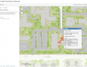
As a final note, our customers prefer to use custom web dashboards like you see here, when it comes to effectively monitoring flow meters, water wells, and water levels.
Lessons learned and things to remember:
- Put some coupling agent or thermal compound between your transducers and your pipes. If you forget this, then your ultrasonic flow meters won’t receive measurements from the sensors / transducers. Note that you can experiment with using substances like vaseline, liquid soap, or any other lubes as coupling agents.
- Remember that there are lots of types of flow meters, so choose which brand and model works best for your scenario. Whether you need to use impeller, propeller, mechanical, magnetic, ultrasonic, or other flow meter technologies, we’re here and ready to help you so please don’t hesitate to get in touch.
- Take extra special care to make sure there aren’t any dust particles, sand, or anything else other than coupling agents. You don’t want anything extra left between your pipe’s outer surfaces and your transducers.
That’s your quick start guide to monitoring your TUF 2000 series ultrasonic flow meters with Tools.Valarm.net. Please don’t hesitate to let us know if we can help you out any further for your water and air monitoring needs. You can contact us at Info@Valarm.net.